Reinforcement Learning for Flexible back Quadruped
Learning gaits using RL for a self designed quadruped
Project: Designing a Quadruped and Implementing Gaits Using Reinforcement Learning
Overview
This project focused on designing a high-speed quadruped inspired by the biomechanics of agile animals like greyhounds. The primary goal was to develop a simulation of a quadruped capable of efficient locomotion by integrating mechanical innovation with reinforcement learning (RL). The project consisted of three phases:
- Simulation of various robot designs to optimize locomotion parameters.
- Development of walking gaits using RL in simulated environments.
- Construction of a modular quadruped for real-world deployment and evaluation.
Here is the link to the github repository.
Simulation and Design Innovations
The initial phase involved extensive simulations in MuJoCo to explore various robot configurations and their impact on locomotion efficiency, with iterative design improvements focused on reducing complexity while enhancing performance. Starting with variations of the Half-Cheetah template, the simulations incorporated design changes inspired by greyhounds to optimize the quadruped’s structure and mechanics for greater efficiency.
Quick Summary of the changes sections:
- Reducing Degrees of Freedom (DoF):
- Simplified the standard 12-DoF configuration to 8-DoF by eliminating hip motors.
- Improved straight-line speed and reduced control complexity while maintaining essential movement.
- Torque Optimization:
- Modeled motor torques to mimic the force distribution seen in greyhounds, emphasizing stronger upper-leg joints.
- Enhanced energy efficiency and stability during high-speed motion.
- Segmented Back Design:
- Introduced a flexible, spine-like back to improve stride length and energy transfer.
- Simulations demonstrated a significant increase in speed and smoother gaits compared to rigid designs.
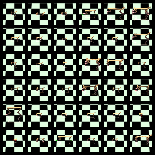
- A Picture Collage of all the different styles
2 Dimensional Design
- Using the half-cheetah model—a 2D, 6-DOF system—I aimed to simplify the design to a 4-DOF configuration, laying the groundwork for an eventual 8-DOF quadruped system. This approach sought to demonstrate that a hip joint is not essential for linear motion. The modifications were explored as follows:
- Removing the foot link: The first iteration involved eliminating the foot link to create a 4-DOF system constrained to linear motion, preventing sideways movement.
- Passive Shin Actuation: The second approach removed the shin motor, allowing the shin to move passively under the influence of the foot and thigh motors while maintaining a 4-DOF setup.
- Passive Foot Actuation: Lastly, the foot motor was removed, enabling passive actuation of the foot, with the thigh and shin motors controlling movement.
- Despite these efforts, the 2D models struggled to achieve effective training results. The primary challenge stemmed from the critical role of the original 6-DOF configuration in maintaining balance during motion. Without it, the system required the legs to move at high speeds to prevent the torso from tipping forward or backward, leading to instability.
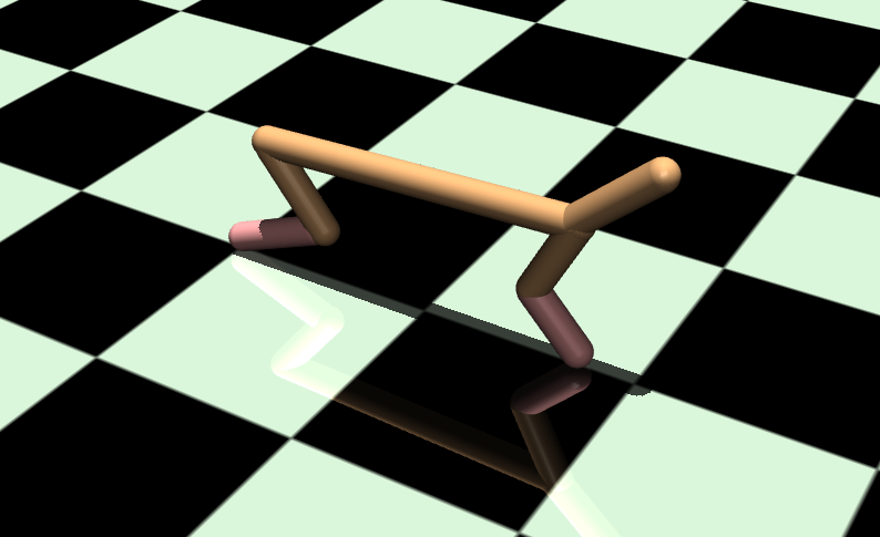
- This exploration highlighted the limitations of simplifying the 2D design, prompting a shift towards developing an 8-DOF quadruped system in 2D. The insights gained from these experiments guided the transition to a full 3D design with four legs, which I will elaborate on in the next section.
4 Legged 3D design
-
Following the challenges encountered in achieving stable gaits without tipping in the simplified 2D designs, I transitioned to modeling a complete 4-legged system. This shift introduced new complexities due to the hierarchical parent-child relationship of links in MuJoCo, necessitating several iterations to ensure the legs were both individually articulated and properly connected to the torso link.
- Initial Design and Y-Direction Constrained Training:
- Once the 4-legged model was successfully constructed, I began training the gaits with a constraint limiting movement to the Y-direction. This approach yielded excellent results, producing smooth forward motion and a natural walking gait for a single-link torso.
- This stage leveraged motor values from the original MuJoCo half-cheetah model and demonstrated the feasibility of stable motion.
- Scaling for Real-World Implementation:
- After achieving promising results in simulation, I refined the model to be more realistic for physical implementation.
- The entire system was scaled down to approximately one-third the size of the original half-cheetah model.
- Motor torques were adjusted to reflect specifications of off-the-shelf components, aligning the simulated design with practical constraints.
- Training in 2D:
- Using the scaled-down model, I trained the quadruped in 2D. This phase was highly successful, resulting in stable walking gaits.
- Unconstrained Gait Training:
- Building on the success of 2D training, I removed the Y-direction constraint to enable movement in all directions.
- This transition opened up new opportunities for refining the model, focusing on achieving balance and developing more versatile and efficient gaits, which will be elaborated on in the reinforcement learning section.
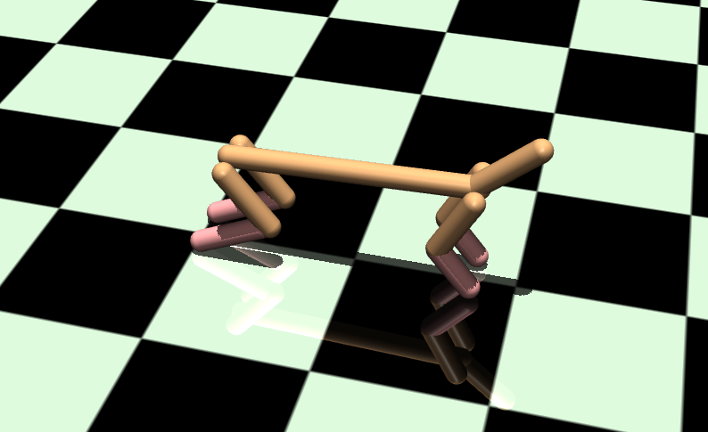
After the successful training of unconstrained gaits, I focused on designing a real-world quadruped based on the specifications derived from the simulation. The details of this physical design process, including hardware considerations, are discussed in the Quadruped Design section.
This iterative approach bridged the gap between simulation and real-world application, providing a robust foundation for efficient quadruped locomotion.
Reinforcement Learning for Gaits
To develop efficient and stable locomotion for the quadruped, a custom MuJoCo environment was designed to integrate the unique features of the robot’s 8-DOF configuration. This environment played a critical role in refining gait patterns through reinforcement learning (RL).
Custom Environment Features
The environment was built to closely model the physical quadruped, featuring:
- Action Space:
- Tailored to the 8-DOF quadruped, the action space was designed to ensure precise and efficient motor control.
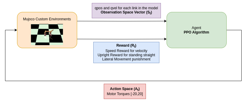
- Torque outputs for the motors were restricted to a range of [-20, 20], aligning with the capabilities of the selected motors.
- This configuration not only facilitated effective simulation but also enabled a seamless transition to real-world torque control.
- Observation Space:
- The observation space was carefully constructed to provide the RL model with a comprehensive understanding of the quadruped’s state. Key components included:
-
qpos and qvel: Representing joint positions and velocities relative to their parent bodies, dynamically adapting to changes in the number of links in the model. -
IMU Feedback:Positioned at the center of the torso, the IMU provided critical data for maintaining balance and posture.
-
- As new segments were introduced, the expanding observation space was systematically managed to ensure consistent performance during training.
- The observation space was carefully constructed to provide the RL model with a comprehensive understanding of the quadruped’s state. Key components included:
- Energy and Performance Monitoring:
- Metrics such as motor energy consumption, speed, and upright posture were meticulously tracked throughout the training process.
- These insights were instrumental in optimizing performance, ensuring that the quadruped maintained stability and efficiency during locomotion.
By combining these features, the custom environment offered a realistic simulation platform that effectively bridged the gap between virtual training and real-world implementation. The reinforcement learning process leveraged this robust environment to develop adaptive and reliable gaits for the quadruped.
Training Process
The quadruped’s locomotion capabilities were developed through a systematic reinforcement learning process using a custom-designed training pipeline. This process included the selection of an appropriate RL algorithm, crafting reward functions tailored to the quadruped’s requirements, and deploying a robust training infrastructure.
- Algorithm Selection and Implementation
- The primary algorithm used was PPO from Stable Baselines3, chosen for its reliability and effectiveness in continuous action spaces. Its ability to balance exploration and exploitation while maintaining training stability made it ideal for the quadruped’s dynamic and complex control requirements.
- PPO’s hyperparameters were fine-tuned to optimize training outcomes, with the key parameters being:
 learning_rate=3e-4,
 n_steps=2048,
 batch_size=64,
 n_epochs=10,
 gamma=0.99,
 gae_lambda=0.95,
 clip_range=0.2,
 clip_range_vf=None,
 ent_coef=0.0,
 vf_coef=0.5,
 max_grad_norm=0.5,
 use_sde=False,
 sde_sample_freq=-1,
 target_kl=None,
 tensorboard_log=log_dir,
 policy_kwargs=policy_kwargs,
 verbose=1,
 normalize_advantage=True,
 device='cpu'
- Exploration of Other Algorithms:
- Alternative algorithms such as Soft Actor Critic (SAC), Advantage Actor Critic (A2C), and Twin Delayed DDPG (TD3) were also tested but did not yield favorable results for this application. These algorithms faced issues in stabilizing the gaits or maintaining efficient learning for the high-dimensional action space of the quadruped.
- Reward Functions:
- Custom reward functions were critical in driving the quadruped’s learning process. These functions were designed to encourage desirable behaviors while penalizing inefficient or unstable actions.
- Successful Rewards:
- Speed Reward:
A significant reward multiplier (10) was applied to the forward velocity to encourage faster and smoother locomotion. - Upright Posture Reward:
To ensure balance, the reward was proportional to the torso’s height relative to the desired upright position, calculated as:
upright_reward = -abs(current_z_position - upright_position)
- Speed Reward:
- Experimental Rewards:
- Joint Position Reward:
Encouraged joint angles to stay within a predefined range, promoting stability.reward = 0 for joint_name, (min_val, max_val) in joint_ranges.items(): joint_angle = self.sim.data.get_joint_qpos(joint_name) if min_val <= joint_angle <= max_val: reward += 1.0 else: reward -= 1.0 - Joint Effort Penalty:
Penalized excessive torque exertion to prevent flailing and promote smooth movement.penalty = 0 for joint_name, max_tor in max_torque.items(): joint_torque = self.sim.data.actuator_force[self.model.actuator_name2id(joint_name)] if abs(joint_torque) > max_tor: penalty -= 0.1 * (abs(joint_torque) - max_tor)While these experimental rewards provided insights, they proved overly complex or less effective compared to simpler strategies.
- Joint Position Reward:
- Training Infrastructure:
- The training was conducted on a headless server to maximize computational efficiency. A virtual environment was created to ensure seamless integration of the training pipeline, which included MuJoCo and Stable Baselines3. All dependencies and configurations are documented in the GitHub repository linked to this project.
Evaluation
Post-training, the model’s performance was rigorously evaluated using logged data and visualized insights.
The RL model’s performance was evaluated through metrics like:
- Performance Metrics:
- Energy Expenditure: Assessed the total energy consumed by the quadruped during locomotion to identify efficient gait patterns.
- Motor Efficiency: Evaluated the torque-to-energy ratio to ensure optimal motor utilization and reduced power wastage.
- Maximum Velocity: Measured the peak velocity achieved during simulation without compromising stability or balance.
- Training Metrics and Model Selection:
- Training progress was monitored using TensorBoard, particularly focusing on value loss, which served as a key indicator of model stability and convergence.
- Comparative analysis of value loss across different timesteps helped identify the best-trained models. Timesteps with consistently lower value loss, indicative of reduced variance and improved learning, were selected for deployment.
- Key checkpoints were analyzed to balance performance and efficiency, ensuring the selected models excelled in metrics like reward accumulation and energy optimization.


The best-performing models were identified by analyzing the value loss curve during training. Models where the value loss steadily decreased and reached near-zero values at specific timesteps produced the most stable and efficient walking gaits. These curves reflected well-converged policies with minimal variance between predicted and actual rewards.
In contrast, models with value loss curves that plateaued early or fluctuated excessively resulted in suboptimal gaits, marked by instability or inefficient motor control. Successful models displayed a clear downward trend in value loss, aligning with balanced, energy-efficient locomotion. Focusing on these timesteps ensured the selection of optimal gaits and refined overall performance.
- Visualization Tools:
- TensorBoard provided real-time insights into reward trends, policy gradients, and loss metrics during training.
- Custom plots for energy consumption, motor power, and velocity trends offered a comprehensive view of the quadruped’s capabilities, aiding in further refinement.
- Trends in the value loss curve were used to validate the effectiveness of training strategies and ensure alignment with performance goals.
This structured evaluation approach facilitated the selection of optimal models while providing actionable insights to guide future iterations and enhance the quadruped’s real-world performance.
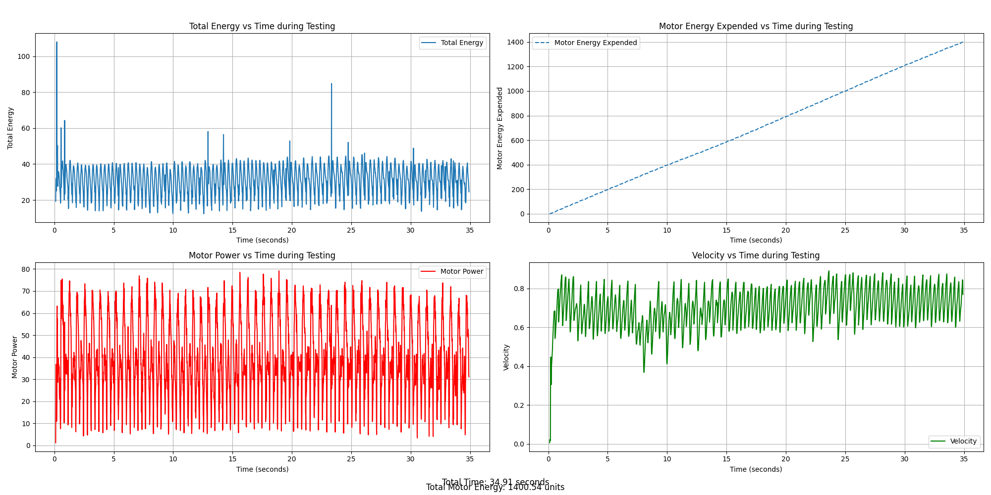
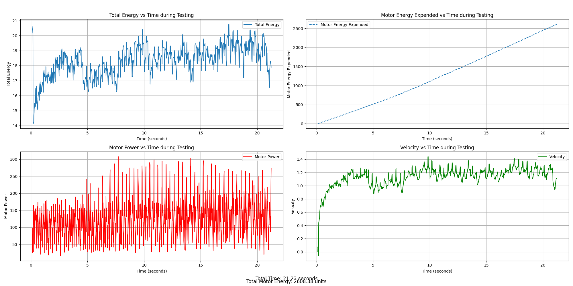
The left cluster of graphs is for a single link torso and the right is for a multi link torso. We can easily compare that the max speed achieved by a segmented back is 1.47 while the single link is about 0.8. This was indicative of the design changes were in the right direction.
Designing and Building the Quadruped
The quadruped design bridged simulation and hardware, featuring modularity, precision actuation, robust electronics, and real-time sensing.
- Mechanical Structure:
- Frame Design:
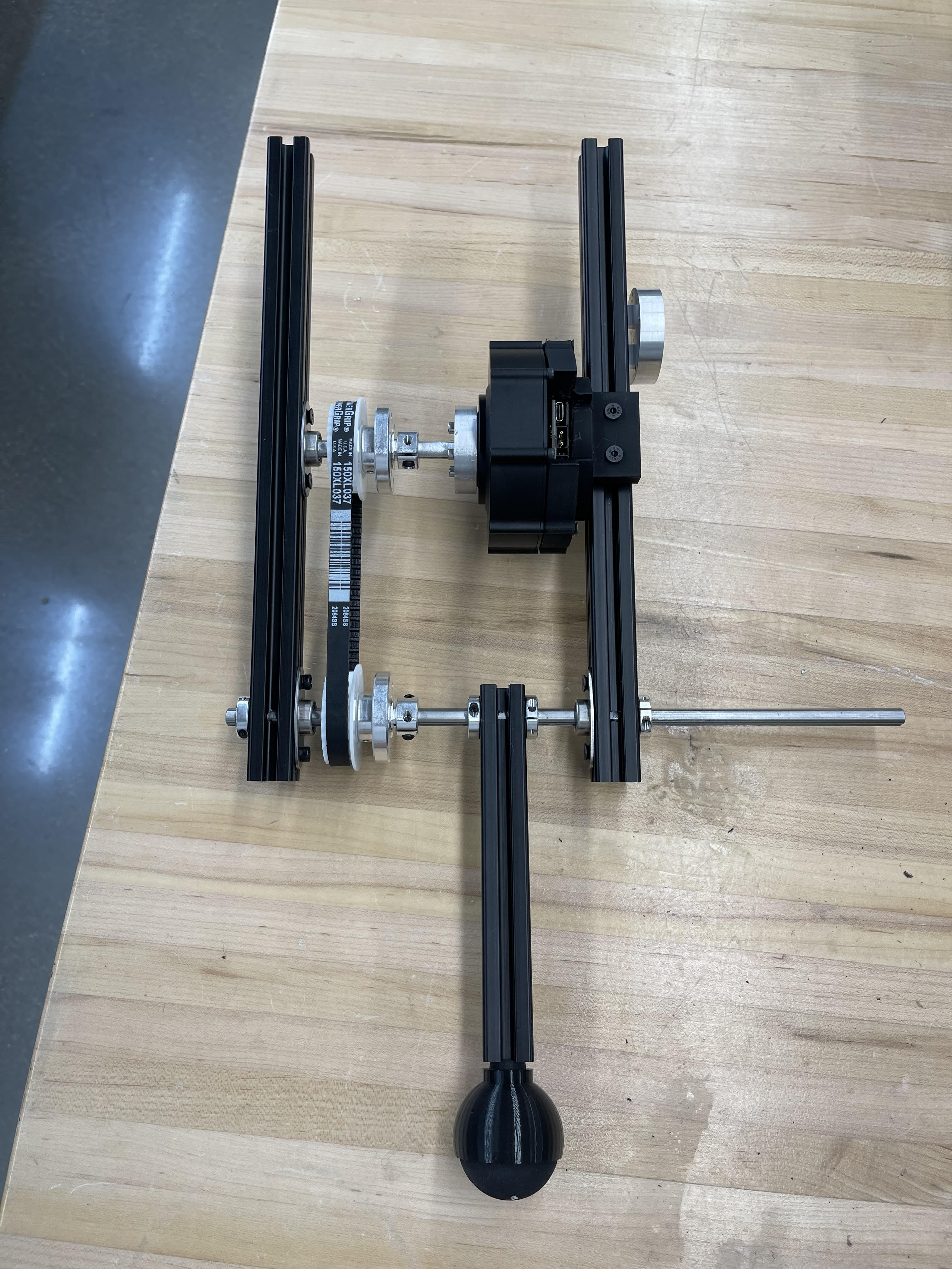
- Built using 20-20 aluminum extrusions for a lightweight yet durable frame. The modular design allows for easy adjustments and upgrades to suit user needs.
- Integrated belt-pulley systems inspired by earlier MIT Cheetah versions provided smooth, efficient leg motion. The 20-20 extrusions facilitated easy belt tensioning.
- Custom Parts:
- Custom aluminum components were designed and manufactured to accommodate high-torque motor assemblies, ensuring durability under load and preventing structural failures.
- Iterative Prototyping
- Continuous design iterations refined the mechanical structure, as illustrated below:
- Frame Design:

- Actuation and Control:
- Motor Selection
- Torque demands from MuJoCo simulations identified a peak of 21Nm for the larger quadruped.
- High-speed brushless DC motors Steadywin GIM8108-8 with a peak torque output of 22Nm were selected to meet these requirements, balancing high rotational speed with lightweight construction.
- The motors come with integrated ODrive controllers for precise control and seamless hardware interfacing, enabling rapid prototyping and tuning.
-
Motor Specifications
- Gear Ratio - 8:1 - Diameter - 97mm - Stall Torque - 22Nm - Nominal Torque - 7.5Nm - No Load Speed - 320rpm - Nominal Current Rating - 7A - Peak Current Rating - 25A - Voltage Rating - 48V - Mass - 375g - The motor information is attached here.
- Motor Selection

- Feet Design
- 3D-Printed Feet:
- The feet were based on a design from Thingiverse, originally used for 3D printers.
- Inspired by the MIT Cheetah, squash balls were utilized for cushioning and durability.
- 3D-Printed Feet:
- Electronics
- Power Supply
- Each motor was powered by a 48V-25A power supply, with one supply handling four motors simultaneously.
- This power supply was selected for its ability to deliver a peak current of 25A, which comfortably exceeds the combined current required by 4 motors for position control.
- Link to the power supply.
- Communication
- A Raspberry Pi 4B, equipped with an RS485 CAN-HAT, facilitated CAN-bus communication with the ODrive controllers for efficient motor control.
- Power Supply
- Sensors:
- IMUs and Encoders:
- Integrated sensors provided real-time feedback for accurate motion tracking.
- These sensors ensured stability and precise replication of the trained RL model’s behavior in physical tests.
- IMUs and Encoders:
Full Quadruped Pictures
Here are some pictures of the fully built quadruped
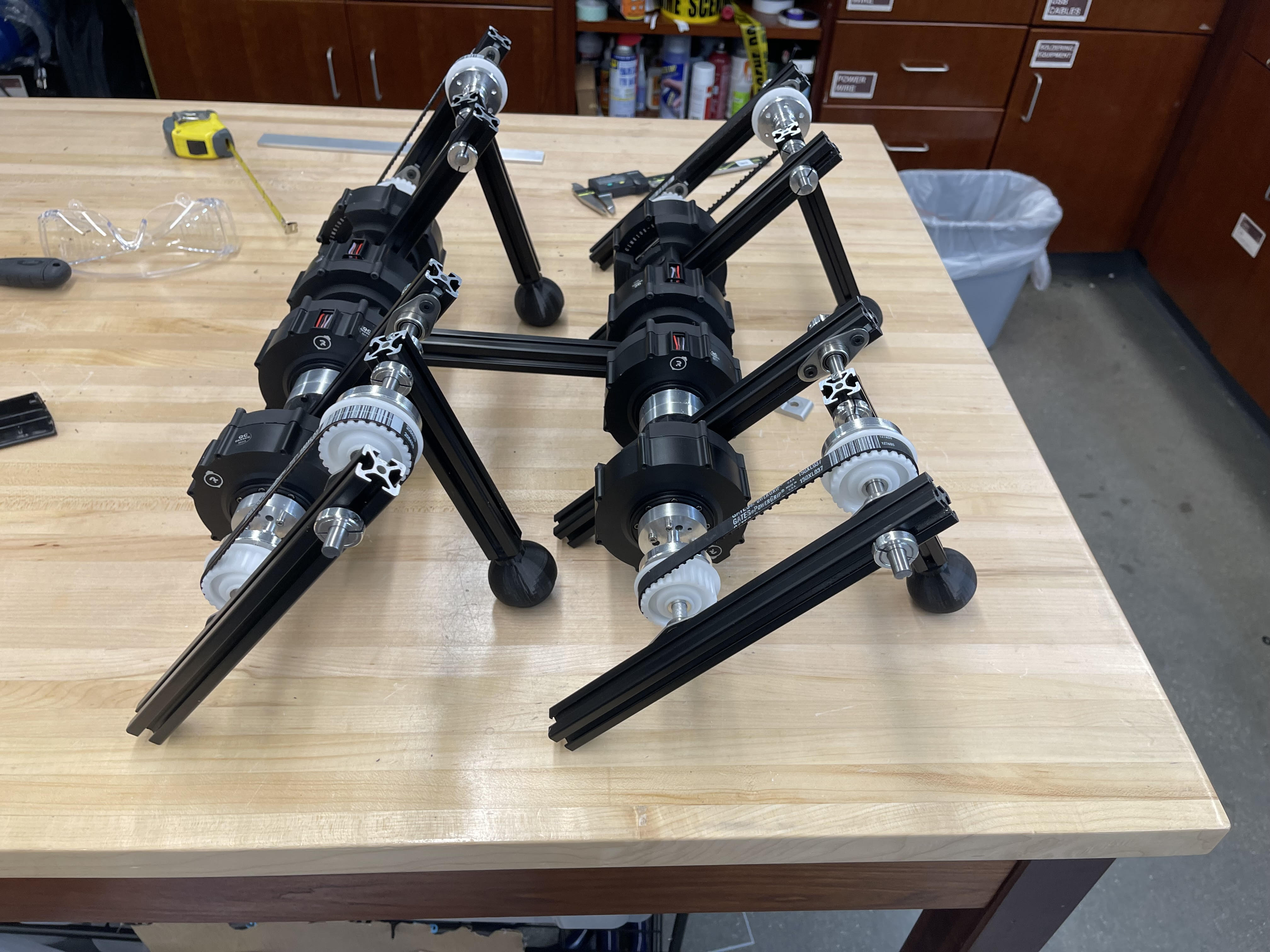
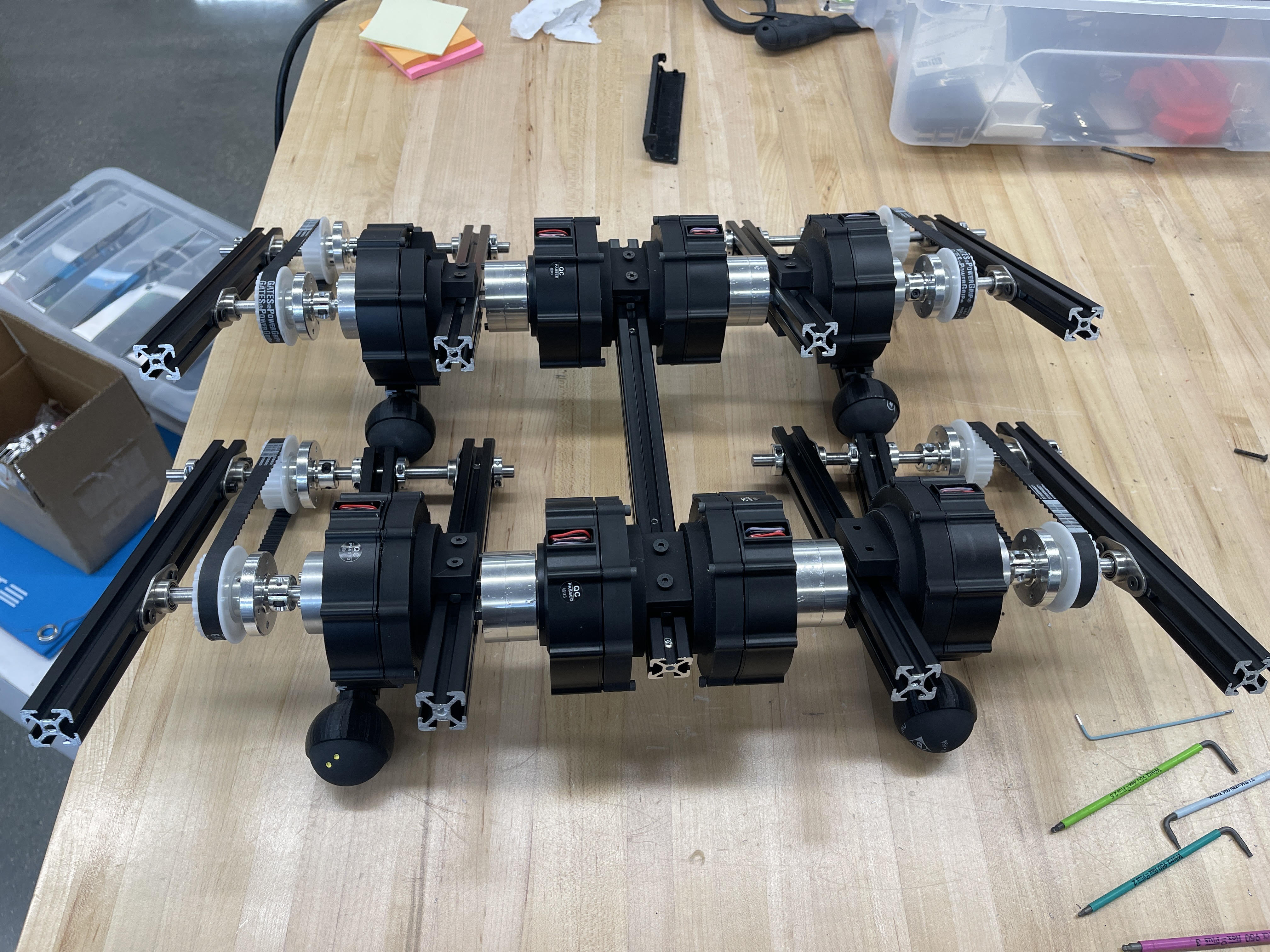
The video on the right shows position control test for motors in home position. The video on the left is a small snipped on the quadruped standing under its own weight.
Sim-to-Real Pipeline
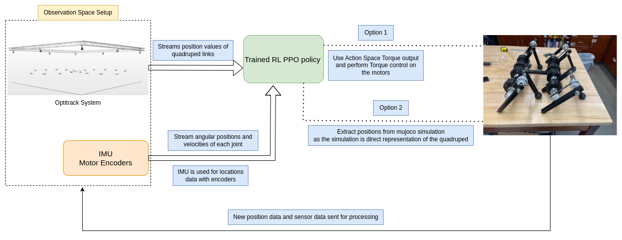
The transition from simulation to reality was facilitated through a well-defined sim-to-real pipeline:
- Direct Deployment:
- The RL trained model can be deployed on the real robot directly as the mujoco model is modelled directly around the real quadruped.
- The action space of the model is torques, so the RL model can be deployed using torque control.
- Another way it can be deployed is using position control and deploying positions for motors which can be extracted directly from mujoco’s physics simulations.
- Here is a layout of how this deployment would work:
- Future Works:
- Plans include integrating OptiTrack or camera-based systems to improve positional accuracy during real-world tests.
- Implementing the segmented back setup on a real quadruped.
- Completing the sim to real pipeline for the built quadruped.
Innovations and Learnings
The project introduced several unique features that improved speed and efficiency:
- Reduced Motors: Achieving high speeds with an 8-DoF configuration reduced cost and complexity while maintaining effective locomotion.
- Segmented Back: Inspired by animal anatomy, this feature significantly enhanced the quadruped’s agility and speed in both simulation and physical tests.
- Custom RL Environment: Developing a tailored environment allowed efficient training and evaluation of locomotion strategies, with detailed metrics for energy optimization.
Working with Stanford Pupper V1
I also worked with a Stanford Pupper before designing my own quadruped. I built and assembled the Pupper V1 kit available on MangDang.com. This particular open-source quadruped was selected for two main reasons: it is completely open-source and easy to fix, and its single-segment back allowed for quick iterations if needed.
- Reinforcement Learning with the Pupper:
- Similar iterations were performed on the Pupper and trained in simulation using MuJoCo. The walking gaits were also converted and implemented on the real robot using an open-loop position control method.
- MuJoCo Models:
- Here are the MuJoCo models of the Pupper used for simulation.
- Issues with the Pupper:
- After completing the open-loop pipeline, I identified several issues with the Pupper that led to designing my own quadruped. These include:
- The goal was to create a very fast quadruped, but this was challenging using hobby servos on the Pupper.
- The Pupper exhibited poor stability and had difficulty walking on tile floors due to its very thin carbon fiber leg design, which caused it to slip. Adding rubber washers to the feet did not significantly improve stability.
- Open-loop control proved insufficient for maintaining stability. These limitations suggested that the Pupper V1 hardware was not suitable for the intended tasks.
- After completing the open-loop pipeline, I identified several issues with the Pupper that led to designing my own quadruped. These include:
- Video of the Open-Loop Control on the Pupper:
Aknowledgements
- Matthew Elwin - For constant support and guidance throughout this project.
- Davin Landry - Helping me with mechanical Design iterations.